Part 1
This is a different story. I have a Crosman 1377 and a 2289 that were bought in the Summer of 1999. Over time they started to loose power due to the hardening of the piston cup. This happened several years ago well before I had any machining capability. At the time I used a cheap solution that was fairly effective.
Using a small round file I grooved a channel around the base of the cup close to where it attached to the plastic piston. Once deep enough a o-ring was installed and the proper pump sealing was restored. I used the same technique on both airguns and they have been working well since then.
When I recently checked both they were still building and holding pressure as expected.
So this project with the 1377 was not a repair but just an excuse to do some machining and spend time in my shop.
After some research, I realized that one of the modifications for that platform is to replace the regular cone tipped valve with a flat top system. The kits are available from several sellers but I thought it might be a nice challenging project for me.
The first step was to get all the dimensions from the existing valve and make a 3D CAD model of a flat top valve and piston.
Since the original is brass, I found a piece that I could use from my limited supply. I cut the thread with a die and checked the fit again the existing one. I was good to go.
In the meanwhile, I was still looking for info on the internet and I came across a post that mentioned that aluminum can also be used for flat top valves. That made me thought that, since I was navigating unknown territories, if I screwed up I was wasting a nice chunk of brass.
So back in the shop, I restarted with a piece of aluminum, recut the thread and, this time, was actually ready to go.
This is a long story but let’s say that most of the operation went well but what was causing me some headache was the bottom of each half of the valve.
One half has the check valve to let the air in but not out and the other has the exhaust valve with the transfer port.
The check valve side has a cone and a smaller flat-bottomed hole. I was not sure if the check valve piston should seal on the flat or the cone but I guessed on the cone. I did a drilling test on a small scrap pf brass and the result with a drill and a small endmill was not too bad. When I tried it in the aluminum it didn’t go so well. The drilling was OK but I got a lot of chatter from the endmill. Anyway I thought that since it should seal on the cone it would work as long as the flat face of the piston is not touching it first.
For the other side with the exhaust port, it is more complicated. Normally the seat valves I have seen until now are mostly a slightly raised thin donut against which the plastic head would seal but I suspect that special tools are needed to achieve that.
Since I don’t have the special tools, I was looking at options I can achieve by myself. Since I made my drawing with a flat seat that is what I decided to try first. The result with the 3/8 endmill was not great due to the shatter so I made a cone with a drill. The result with a 3/8 drill was better but because it was at the bottom of the hole it was difficult to evaluate the actual surface finish.
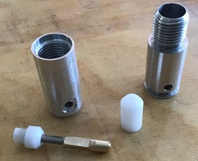
Since it was the best I could do for now, I started working on the valve stem. I am really bad at documenting my project and I should have taken more pictures. The 1377 has a strange shaft, on a short distance it has a smaller diameter close to the sealing head (probably to give a better airflow) then it grows bigger to fit in the exit hole. Instead of being round this larger shaft has four flats.
Attachment:
 01.JPG [ 130.5 KiB | Viewed 721 times ]
Since I am not very experienced machining in steel I decided to use the same 1/8” steel rod as the one from my other repairs and to make a brass sleeve with a blind hole for the larger diameter. I figured that the tip of the larger brass sleeve didn’t have to be flattened all the way and I left it round. Delrin was used for the head at the other end and it was tapered to the same angle as the drill tip.
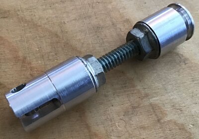
I tried this version of the valve in the airgun but because I still had the piston with the cup the air was not going in. This meant I needed a flat top piston. I had made my CAD drawing as a one-piece aluminum piston the length of the plastic piston with the cup on. After reading more posts on the internet I chose to make it adjustable but after several length tests in the pistol it finally ended up being exactly what I had figured in my drawings.
With a complete matching set, I couldn’t pressurized the airgun. Maybe the project was a bit too ambitious. Was it leaking between the piston and valve o-rings, was it the check valve not doing its job or the exhaust stem leaking. Furthermore my aluminum piston was rubbing inside the tube.
Attachment:
 02.JPG [ 155.45 KiB | Viewed 721 times ]
This needed some detective work and some filing of the piston.
Pushing was not doing anything but pulling the piston out made a popping noise so I guessed the check valve was working and both the piston and valve o-rings were sealing. The answer was that the culprit was the exhaust valve stem.
In order to verify my assumption I reverted to the original setup using my exhaust half of the valve. The result was leaking from the exhaust stem again. This meant I needed to go back in the shop for more work.
I decided to go back to a flat bottom with a small boring bar. Because it was at the bottom of the deep hole it was difficult to evaluate the actual surface finish but it looked better than the result with the endmill.
I did another stem with a brass sleeve but with a flat Delrin head to match the new bottom of the valve. After lubing and reinstalling the new configuration, it was leaking until it finally started to hold air. I tried it repeatedly over and over and it made a popping sound every time I pulled the trigger. It was looking better than before. I noticed that the tube was getting fairly warm so I pressurized it another time and left it alone for 5 minutes then it shot as before so I went through the cycles several times again and decided to left it alone for an hour this time.
Deception!!! When I pulled the trigger, I just heard the hammer hitting the valve stem. All the attempts to pressurize it again failed. I am not sure if there was a relation with the pistol being warm or cold but it was not a success for sure.
I thought that maybe the valve stem needed to be seated better and warmed up the metal and the Delrin before smacking it hard. I probably went a little too far with heating the Delrin because when I got the stem out from the valve it was deformed. As it was useless, I decided to make another one.
In the meanwhile, I had come across a large nail that had the right diameter, so I machined my new shaft directly from it and the Delrin head was cut with a flat face, a chamfer on the periphery to reduce the contact area and a slight donut projection around the metal shaft to match the larger hole in the valve body. I was hoping that it would also help to seal. Again, it failed.
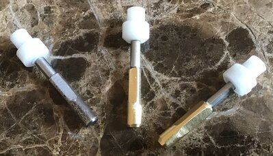
This picture shows the different Valve Stems I made up to this point.
Attachment:
 03.JPG [ 260.85 KiB | Viewed 721 times ]
Maybe a conical seat would be better. I still had my first valve stem so I drilled the bottom of the valve to get a cone to match it and also machined the end of a hardwood dowel to the right profile hoping to use it to smooth the drilled surface. I was not sure what to use but I had a small bag of fine sand and after dipping the tip of the dowel in glue and in the sand, I placed it in my drill chuck and spun it inside the valve with a little bit of loose sand. It seemed that my fine sand was still too coarse because I ended up getting a series of concentric lines instead of a single smooth surface. I went at it with another dowel and toothpaste but it didn’t really change anything. Since I already had the stem and I thought that maybe the shallow concentric grooves between the lines would retain some silicone grease and that it might seal, I gave it a try. Nope… it didn’t work either.
The end result was that the original valve and piston have been reinstalled and the pistol reassembled.
R-Gun Pete


