In May 2016, I bought a first Crosman Model 622 from Mr Marvin. From the information I collected from different sources, it seems to be an unaltered earlier version (made before September 1972).
Due to an inherent design weakness, the valve is prone to stretching or breakage close to the single screw holding the pressure system.
Over time some modifications were made by Crosman to address several problems encountered by users. Those modifications could have been made at the factory or by a service center. The left side receiver has a short locating boss to lock the pressure tube in position but unfortunately the tube would sometime slipped out putting all the CO2 pressure on the valve body. After September 1972, the left receiver was modified with a longer locating boss. To prevent pellet jamming, after March 1973, the chamber portion of the barrel have been opened up with a reamer. Sometime, a vacuum would occur in the pressure tube preventing the release of the Powerlet, since September 1973, there is a hole through the receiver halves and the tube to help removal. To solve a problem with the Pell Clip jamming, a Clip Extractor has been added starting in November 1973.
Knowing all that, I was left with the dilemma of fixing the potential valve problem on a Crosman 622 that works perfectly fine. Should I leave it alone and wait until the leaking problem appears or should I made the preventive modification to prolong the valve life?
My problem was that I read a lot about that modification but couldn't find any specification on how to perform it. I was hesitant to experiment on my 622 in excellent condition.
This rifle came with a single clip, so I thought that I could redesign a new one that could be rapid prototyped. As I couldn't take apart the only one in my possession, I had to be creative about the internal detent that stopped the wheel at the proper spot.
In the meanwhile, I was looking to buy extra clips (difficult to find and expensive) when, in late June, I came across a 622 advertised as in working condition and coming with several extra clips. As the price was interesting, I bought it. After testing it at home I discovered that it was leaking bit and it has a problem with indexing the clip. This forced me to remove it, indexing it by hand and put it back in the rifle for every shot.
The situation gave me the idea of modifying my first clip design to transform it into a manual indexing clip. I removed the ratchet teeth, offsetted the wheel so I could turn it with my thumb from the outside and adjusted the shape of the clip body accordingly.
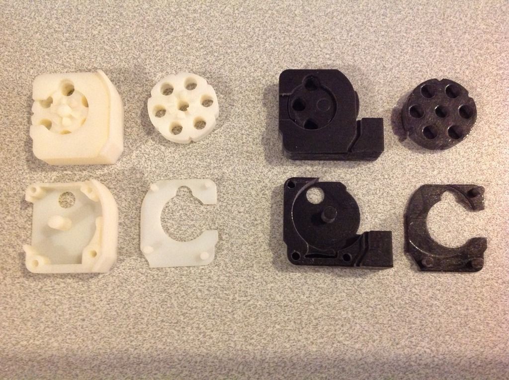
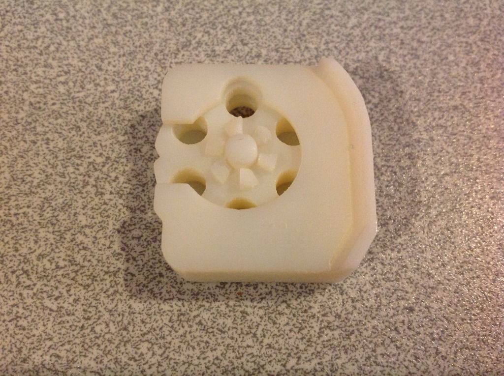
This picture shows the result of both types. The one in white is the replacement for the original indexing clip. Unfortunately the plastic of the high resolution3D printer (cured with UV light) is not stong enough. After several cycles through the rifle the teeth started to break off. The black one, being a lot simplier and indexed by hand, seems to survive a lot better. (The black or the white are the same plastic material, it is just what was installed in the machine when I was ready to make my prototyped parts).
After a few CO2 cartridges, the slow leak of the second rifle became a full blown one. It was now in non-working condition so a perfect candidate for open heart surgery.
This rifle has probably been manufactured after 1973 (or at least has been serviced after that date) because it has some of the factory mods mentioned earlier (Clip Extractor, hole in the tube for Powerlet removal and reamed barrel). As for the left receiver I am not sure about it. There is a locating boss but, having no reference, I don't know if it is the short or the long version.
I would guess it is the short boss as the valve has been subjected to high pressure and the hole was deformed. Luckily it was not broken as I, later, discovered after opening it.
Having finally found a copy of the Factory Service Manual, I was ready to experiment on my dead corpse.
To work on the Valve group, it is not necessary to disassemble everything. I wanted to document the whole process but I didn't do a great job at that. Basically I would need to clean my greasy hands each time I wanted to take a picture with my I-Pad and once I got concentrated on repairing the components I realized that I forgot to take a photo before it was fixed.
Anyway, removing the butt, barrel, piercing rod and forearm groups is fairly easy.
To remove the right hand receiver, some care should be taken to keep the hammer and trigger group together as a single unit. To do so, a pin is inserted as the Trigger screw is removed. The Valve Body screw is also removed and the Right Receiver can be carefully lifted.
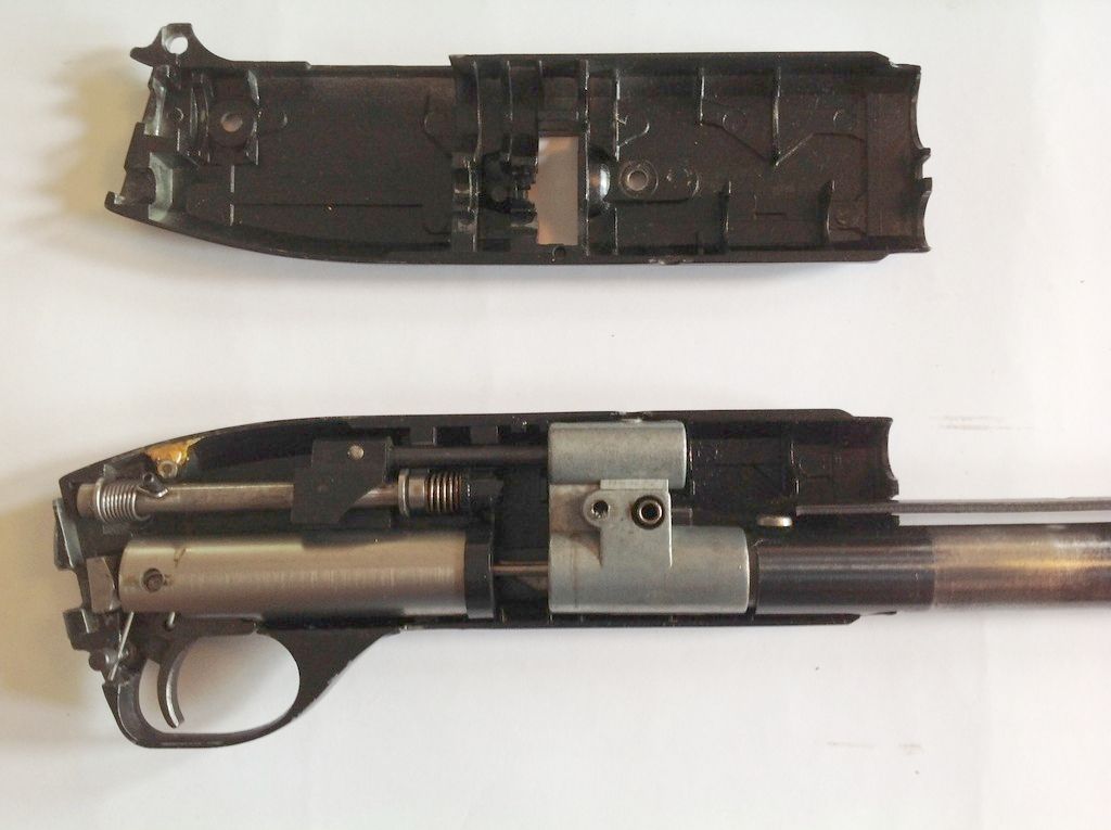
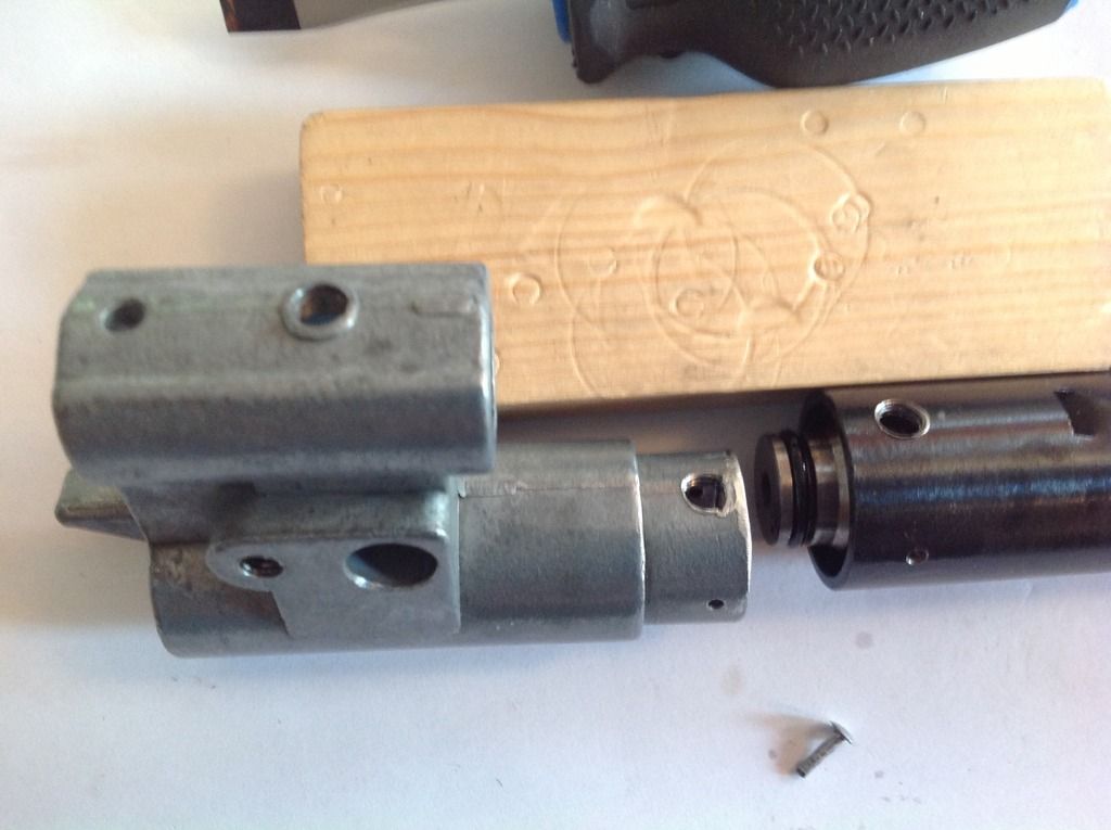
The reference position of the internal components is critical so a couple of pictures were taken.

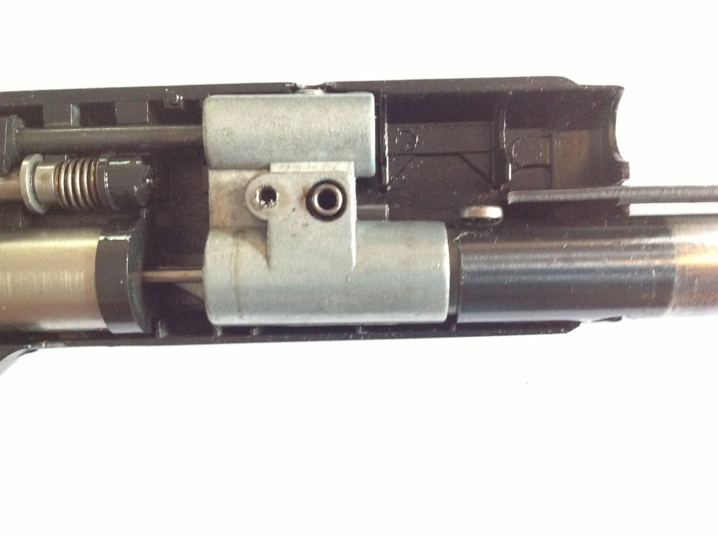
The large gap between the valve body and the tube can be noticed. In the next picture, the valve components are spread away. By looking closely at the spot were the screw was entering the valve body we can see some stretched material. Unfortunately, the angle is not good to show the damage as it doesn't look that much but the hole was really an oval instead of a circle. There was probably close to a half diameter strech.
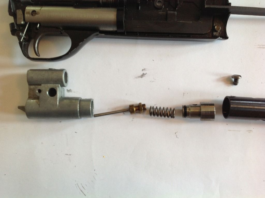
I should have taken a picture before hammering the material back in place but I thought of it too late.
The hole is slightly damaged (as seen in the photo above) but the screw can nevertheless thread in it. As the metal is weakened, it can only be used as reference for holding the parts (pressure tube, valve body and piercing unit body) in place during drilling. The depth was gauged to the bottom of the threaded hole and transfered on a small drill (1/16").
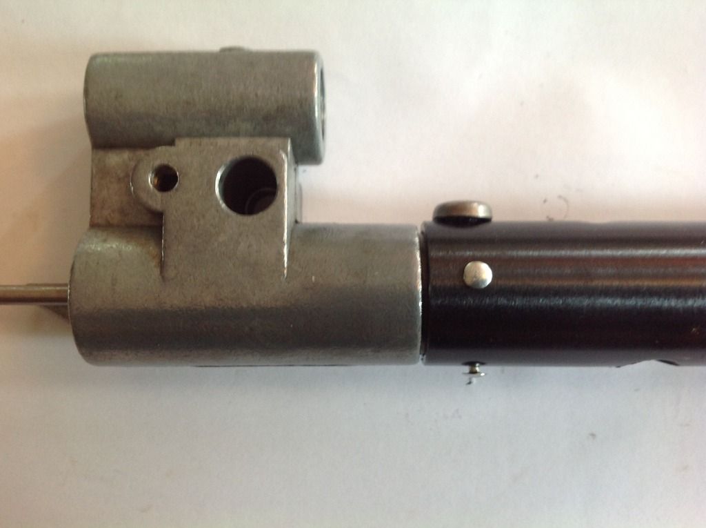
With the components in place (without the spring to avoid any pressure during drilling), 3 holes were drilled (the screw being at 0, the holes are 90, 180 and 270 degrees).
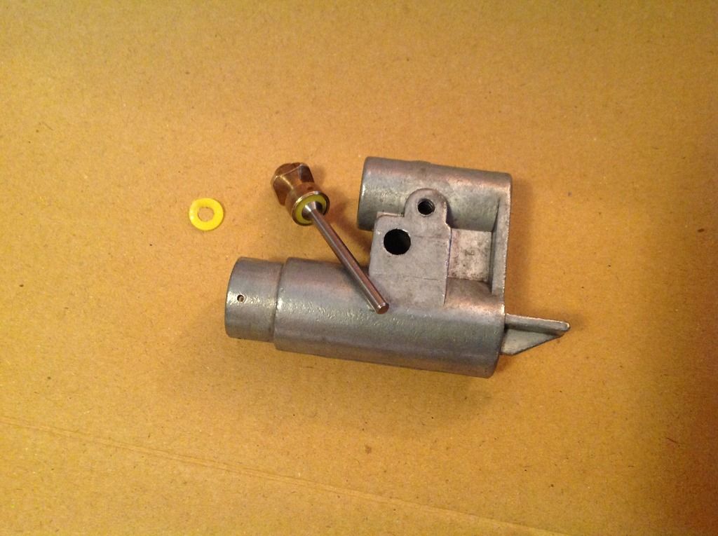
Prior to reassembling the rifle, I changed the o-ring on the piercing unit body. The old face seal on the valve stem (which crumbled in pieces) was also replaced by another o-ring that seems to fit. It was of a slightly larger diameter than the stem outer diameter but it was massaged in place.
Just before getting started to put back the Valve group in the receiver, I made the mistake of touching the Link assembly (bolt and indexing system) and it popped out driven by spring pressure. This was a major pain to put it back together because of the spring that needed to be anchored. I finally had to resort to dental floss to help me control it.
Once the rifle was reassembled, it was pressurized and was holding CO2 perfectly but the indexing problem was still there (that was the reason for the design of the manual indexing clip shown at the beginning of the post).
In the following days, I shot several Powerlets without any glitches. Unfortunately, after having it stored for a couple of weeks, the next time it was pressurized all the gas escaped through the loading port of the clip. This indicated that I had a major leak at the valve stem.
Effectively, when I dissembled the valve, I discovered that the o-ring had swollen and came out on one side. There was not point to put it back flat because it will do the same thing again. The next smaller size of o-ring was not big enough to fill the space.
Previously, I did a repair on a Crosman Mark I and after a couple of years of use, it still hold CO2 when pressurized. Based on that success I decided to use the same technique for the 622.
The secret is simple. The plastic from a coffe can or a yogourt container cover is very smooth but still a bit flexible. The idea is to replicate the thickness of the original seal. For the Mark I one layer was enough (I tried 2 but the gun barely spat the pellet so I had to dissassemble it again to go back to one layer and it worked fine since then). In the case of the 622, two layers filled nicely the stem cavity. The outside diameter was cut with a hollow punch and the small hole with a leather punch. The trickiest part was to obtain concentricity.
Since the plastic is just flexible enough, pushing the stem again the face of the valve seat would sit the plastic piece in the cavity. After that, I just had to finish pushing the edge of the hole under the tapered portion of the stem with my fingernail. It was repeated again for the second layer which provided the perfect thickness.
This time the reassembly was easier because I had tie-wrapped both the link and trigger/hammer groups to the frame so they wouldn't jump out. I also discovered that the indexing pawl had to go the other way. There is some info in the manual about an oval shaped detent spot on the flange. I suppose the tiny mark that I discovered on the part was it because the new orientation seemed to have solved the issue.
This time the rifle is holding pressure and also indexing correctly.
The repair is complete.
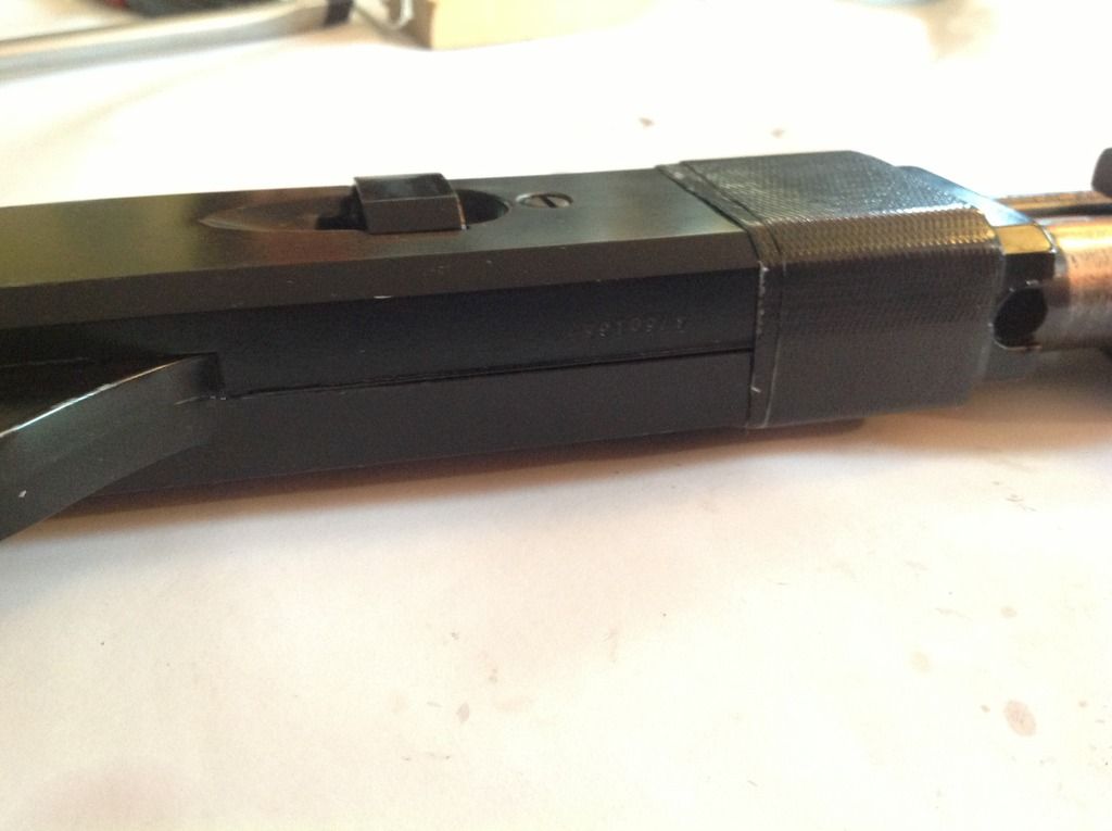
A small gap between the two halves is noticeable even when the screws are completely tightened. Just to make sure that the pressure tube will stay on the boss and prevent damage to the valve, I added a strip of black duck tape to close the small gap. It is not the most elegant look but it could be removed anytime if I would prefer so.
If you need to fix your 622, don't be afraid to try it. I suggest that you find the Factory Service Manual and study it before starting, after that, take your time and enjoy (or at least don't stress too much).
Good luck and have fun.
R-Gun Pete


 [/URL]
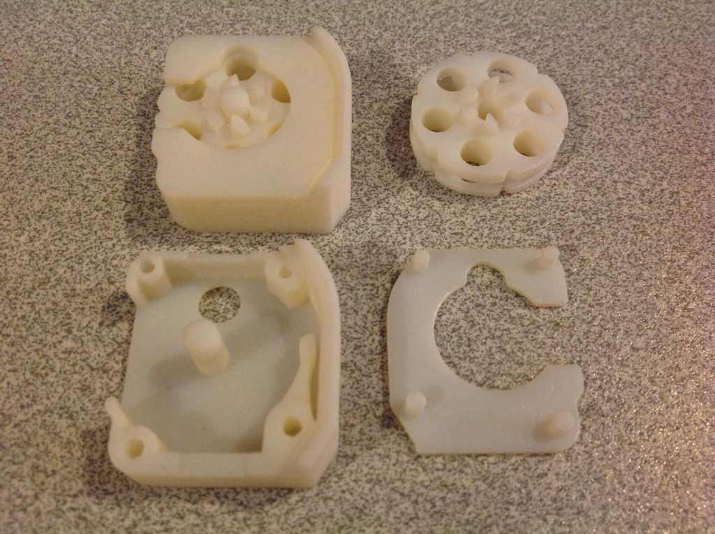 [/URL]
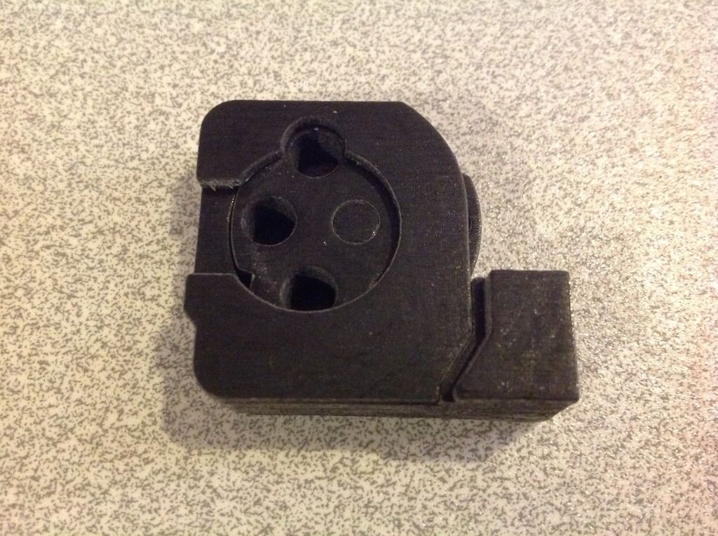 [/URL]
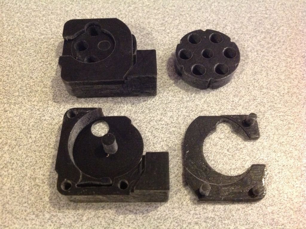 [/URL]